


What Is a Centrifugal Flow Fan and How Does It Work?
A Centrifugal Flow Fan moves air by changing its direction and energy. Air enters through the fan’s central inlet, where a rotating impeller catches it. The blades push the air outward, away from the shaft. Inside the curved housing, often called a volute, the air is guided toward an outlet. That turn matters. In many installations, the outlet carries air away at roughly a right angle to the inlet.
The idea sounds simple. The details matter. Blade shape, rotational speed, air density, and duct resistance all affect performance. A backward-curved impeller, for example, behaves differently from a forward-curved or radial-blade design. The fan’s pressure-flow curve can help match a model to a real system, such as an HVAC duct or an industrial ventilation line. A fan that looks powerful on paper may deliver less air when connected to narrow ducts, filters, or sharp bends. Blocked passages are not something the fan can simply overcome.
This guide explains the main components, airflow path, and factors that influence fan selection. It also looks at noise, vibration, and routine inspection, because these practical details are easy to overlook. A diagram can clarify the airflow, but it cannot capture every installation condition. That limitation is worth remembering. For a specific application, compare manufacturer data with measured system requirements, and follow the equipment instructions.
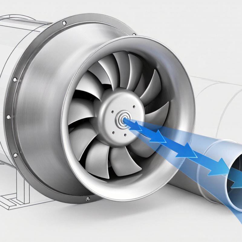
Definition and Purpose of a Centrifugal Flow Fan
A centrifugal flow fan moves air by converting rotational energy into airflow and pressure. Air enters near the center of a spinning impeller, then travels outward through curved blades. The fan casing guides this faster-moving air toward the outlet. Air moves inward, then outward. This design is useful when a system needs steady airflow against resistance from filters, ducts, or equipment.
Its purpose is not simply to move air, but to deliver the flow and pressure a ventilation or process system requires. The U.S. Department of Energy’s Improving Fan System Performance sourcebook estimates that fan systems use roughly 7% of electricity in U.S. manufacturing. That figure makes proper selection and control worth attention. A fan that is too large may waste energy or create excess noise; one that is too small may fail to meet airflow needs. Real systems also change as filters collect dust. That detail is easy to overlook.
Tips: Check the required airflow and static pressure before choosing a fan. Keep filters clean, and verify airflow after installation. A quiet fan is not always an efficient one.
What Is a Centrifugal Flow Fan and How Does It Work? — Definition and Purpose
| Dimension | Description | Purpose or Practical Significance |
|---|---|---|
| Definition | A centrifugal flow fan is a mechanical device that uses a rotating impeller to move air or gas. In a typical design, fluid enters near the center of the impeller and leaves its outer edge in a direction broadly perpendicular to the inlet flow. | It moves air through ducts, equipment, and other systems, including applications where the airflow must overcome resistance. |
| Airflow path | Air commonly enters through an inlet aligned with the impeller shaft, travels through the rotating impeller, and exits around the impeller’s circumference into an outlet passage. | The change in flow direction distinguishes a centrifugal fan from an axial fan, in which air generally travels along the fan shaft. |
| Impeller | The impeller consists of a hub and blades that rotate to transfer energy to the air. Blade shape and orientation vary by fan design. | Impeller geometry influences airflow, pressure capability, efficiency, and suitability for different operating conditions. |
| How pressure is produced | Rotation accelerates air outward through the impeller. The resulting airflow and pressure rise are influenced by the impeller and the surrounding casing or outlet arrangement. | The fan provides the pressure needed to move air through system components such as filters, coils, ducts, and grilles. |
| Volute or casing | Many centrifugal fans use a casing, often shaped like a volute, to collect air discharged from the impeller and guide it toward the outlet. Some designs use different casing arrangements. | The casing helps direct the discharge flow and can help convert part of its velocity into static pressure. |
| Drive and rotation | An electric motor or another power source turns the impeller, either directly or through a transmission such as a belt drive. | Drive type and operating speed affect the fan’s delivered airflow and pressure. The motor must be selected for the required operating conditions. |
| Typical purpose | Centrifugal fans are used for ventilation, heating and air-conditioning systems, process air movement, and equipment cooling. | They are useful when air needs to be routed through a system that creates resistance, rather than simply moved across an open area. |
| Common design variations | Common impeller categories include forward-curved, backward-curved, and radial-blade designs. Their performance and suitable applications differ. | Selection should be based on the required airflow, system pressure, air characteristics, efficiency needs, and operating environment. |
| Key selection factors | Important factors include required airflow, total system pressure, air temperature and density, available space, noise limits, and the resistance of connected equipment and ductwork. | Matching the fan to the system helps it operate closer to its intended duty point and avoids relying on airflow ratings alone. |
| Operating note | Actual airflow depends on the interaction between the fan’s performance characteristics and the resistance of the connected system. | A fan’s stated maximum airflow does not necessarily equal the airflow it will deliver once installed in a system. |