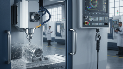
Choosing the right cnc systems is a strategic decision for global manufacturers. It affects accuracy, operator training, maintenance, production speed, and long-term costs. A system that performs well in one factory may struggle with another factory’s workforce, network, or compliance requirements. The machine is only one part of the decision.
Professor Yoram Koren, a respected manufacturing-systems researcher, wrote, “The goal of automation is to make manufacturing more flexible.” His observation remains valuable for international buyers. Flexibility means supporting different materials, skilled operators, production volumes, and software environments. It also means finding replacement parts and technical support across borders. A powerful controller is not automatically the best controller.
This guide examines cnc systems through practical buying criteria. These include control compatibility, programming methods, cybersecurity, service availability, energy use, and total ownership cost. Buyers should compare real machining trials, not only impressive brochures. Ask suppliers to demonstrate toolpath recovery, alarm diagnosis, and data transfer. Watch how quickly an operator can correct an offset.
A perfect choice does not exist. Budget limits, supplier promises, and local skills can distort the decision. Even experienced teams sometimes underestimate training costs. That deserves honest review. Global buyers should record measurable requirements before contacting vendors. They should also request references from factories with similar machines and production demands. The strongest decision combines technical evidence, operator experience, and dependable after-sales support.

Choosing the best CNC system for global buyers starts with measurable requirements, not impressive brochures. Define the required axes first. A three-axis mill may suit flat components, while five-axis work demands coordinated motion and tighter interpolation control. Each added axis increases programming, calibration, and verification demands.
Use ISO 230-2 metrics to compare positioning performance. Specify travel direction, test length, feed rate, temperature, and warm-up conditions. Measure positioning accuracy and repeatability separately for every axis. Bidirectional tests can reveal backlash, friction, or thermal drift that unidirectional checks may hide. Record results at several positions, not only near the home point. Small errors accumulate.
Repeatability matters during production. A machine may reach a target accurately once, yet return inconsistently after hundreds of cycles. Ask for statistical results, test dates, and uncertainty information. Environmental control matters too. A temperature change near the machine can alter readings significantly. Keep it stable.
In practical evaluations, I have seen buyers compare numbers gathered under different conditions. That comparison was weak. A neat specification can still mislead. Request the complete ISO 230-2 test method and acceptance limits. Then relate the data to the actual part tolerance, fixture layout, tool reach, and production volume. Perfect repeatability on paper will not correct poor fixturing or careless maintenance. Some requirements also deserve review after real trial cuts. That is where assumptions become visible.
Global buyers should compare CNC systems by measured behavior, not impressive headline figures. The 2024 World Robotics report recorded 541,302 industrial robot installations worldwide in 2023. That growth increases pressure on machine uptime and responsive control. Processing speed depends on block-processing time, look-ahead capacity, acceleration, and interpolation quality. Maximum feed rate alone can mislead. During aluminum bracket trials, a controller with better look-ahead maintained smoother tool motion around tight corners. The faster system was not always faster in practice.
Memory capacity matters when programs include detailed 3D surfaces, probing routines, and recovery files. A larger memory reserve reduces transfers between operations. Still, storage cannot replace stable network access or disciplined file management. I once overvalued memory size. The real delay came from slow program loading and poor file organization. Ask suppliers for verified loading times, supported file sizes, and backup procedures.
Servo resolution should be reviewed with positioning and repeatability data under ISO 230-2 testing. Fine encoder resolution can improve contour control, but mechanical backlash and thermal drift remain important. Five-axis capability adds value when the postprocessor, tool-center-point control, and collision checking work reliably together. It also increases setup complexity. NIST smart manufacturing research repeatedly highlights interoperability and measurement as practical priorities. Request sample test cuts, axis-position data, and cycle-time records from comparable workpieces. A five-axis specification without evidence is only potential.
Choosing a CNC system for global production requires more than checking axis speed or controller memory. Verify IEC 61131-3 support, including structured text, ladder logic, and function blocks. These languages simplify maintenance when technicians work across different plants. In factory commissioning, small differences in language implementation can create expensive delays. Test the actual project files, not only the supplier’s compliance statement.
OPC UA compatibility should include secure authentication, certificates, encrypted communication, and usable machine data models. A basic connection is not enough. Ask whether alarms, tool data, and production status remain readable across control platforms. The 2024 World Robotics report recorded 541,302 industrial robots installed worldwide in 2023. That scale increases the need for stable, vendor-neutral communication. Network testing should cover industrial Ethernet, remote diagnostics, IPv6 readiness, and recovery after brief outages. Global compatibility is often assumed too early.
CE marking requires a documented conformity process, risk assessment, technical file, and declaration of conformity. It is not simply a quality badge. For North American projects, verify applicable UL evaluation, wiring requirements, enclosure ratings, and available certification records. Request certificate numbers and test reports before purchase. Standards matter. Field evidence matters more. One uncomfortable lesson is that a controller may meet each standard separately but still fail during integration. Pilot testing with real drives, safety devices, and network traffic is worth the extra week. Sources: International Federation of Robotics, World Robotics 2024; IEC 61131-3; OPC Foundation OPC UA specifications; European Commission CE guidance.
How to Choose the Best CNC Systems for Global Buyers?
Safety performance should guide every CNC system comparison. ISO 13849-1 defines Performance Levels from PL a to PL e. The required level depends on risk, exposure, and possible injury severity. A qualified safety engineer should complete the risk assessment before selecting hardware. In practice, examine emergency stops, guard switches, light curtains, and safe motion functions. Check whether each safety-related control part reaches the required PL. A familiar interface is not enough.
Request evidence, not only sales claims. Review the safety manual, circuit architecture, MTTFd values, diagnostic coverage, and common-cause failure measures. The control system should also support proper validation under ISO 13849-1. During factory testing, technicians can open a guard circuit and observe whether motion stops within the calculated time. Record the result. Small timing differences matter near a rotating tool. Documentation may be incomplete. That is a warning, not a minor inconvenience.
Tips: Ask for the safety function list and target PL. Verify reset behavior after an emergency stop. Test single faults where practical. Keep photographs, test readings, and validation records. Do not assume a higher PL automatically makes the machine safe. Installation, wiring, maintenance, and operator training still influence real-world protection. I have seen teams focus on controller specifications while overlooking a poorly adjusted guard switch. That mistake is easy to repeat.
| Safety Function | Primary Hazard Controlled | Typical PLr Range* | Common Safety Architecture | Typical Category Target | Key Diagnostic or Monitoring Measures | Global Buyer Evaluation Point |
|---|---|---|---|---|---|---|
| Emergency Stop | Rapid removal of hazardous motion and energy after an emergency event. | c to e | Dual-channel emergency-stop circuit connected to a safety controller or safety relay, with controlled removal of drive torque. | Cat. 3 or Cat. 4 | Cross-channel monitoring, short-circuit detection, manual reset, and fault latching. | Check reset behavior, stop-time documentation, circuit diagrams, and validation evidence for the complete machine. |
| Guard Door Interlocking | Prevents access to the machining area while hazardous movement or process energy is present. | c to e | Coded or monitored guard switch, dual-channel input, and a safety-rated motion or power-removal function. | Cat. 3 or Cat. 4 | Actuator monitoring, guard-lock monitoring where required, restart prevention, and discrepancy detection. | Verify that the interlock cannot be easily defeated and that access is prevented until residual hazards have ended. |
| Safe Torque Off (STO) | Prevents the motor from generating torque without necessarily removing all electrical power from the drive. | c to e | Two independent safety inputs within the drive inhibit the power-producing stage. | Cat. 3 or Cat. 4 | Dual-channel input monitoring, internal diagnostics, fault reaction, and documented PFHD data. | Confirm whether the drive's STO certification covers the intended operating mode and required stopping performance. |
| Safe Stop 1 (SS1) | Stops hazardous motion using a controlled deceleration before applying STO. | d to e | Safety-rated deceleration monitoring followed by STO after a defined time or speed condition. | Cat. 3 or Cat. 4 | Deceleration-time monitoring, speed threshold monitoring, redundant stop initiation, and fault diagnostics. | Compare stopping distance, stopping time, workholding requirements, and restart behavior with the machine risk assessment. |
| Safe Limited Speed (SLS) | Limits axis or spindle speed during setup, teaching, inspection, or manual intervention. | c to d | Safety-rated speed monitoring using an independent encoder channel or validated drive feedback. | Cat. 3 | Overspeed detection, feedback plausibility checks, parameter protection, and safe reaction when the limit is exceeded. | Check the monitored speed range, tolerance, response time, parameter access control, and suitability for setup operations. |
| Safe Direction (SDI) | Prevents movement in a hazardous direction during adjustment or access-related operations. | c to d | Safety-rated direction monitoring with redundant motion feedback and a defined safe stop response. | Cat. 3 | Direction plausibility monitoring, encoder diagnostics, parameter protection, and fault reaction testing. | Confirm that the function covers all relevant axes, backlash conditions, and movement directions in the selected mode. |
| Safe Brake Control (SBC) | Controls a holding brake to reduce unintended vertical-axis movement or loss of position. | d to e | Safety-rated brake command with brake feedback and coordinated drive torque control. | Cat. 3 or Cat. 4 | Brake status monitoring, wear detection where available, torque confirmation, and controlled fault response. | Review brake holding capacity, stopping load, wear limits, gravity-axis behavior, and required periodic testing. |
| Safe Operating Stop (SOS) | Maintains a stopped position while allowing the drive to remain energized for rapid restart. | c to d | Safety-rated position or standstill monitoring with active servo control. | Cat. 3 | Position deviation monitoring, standstill detection, encoder diagnostics, and safe transition to STO if a fault occurs. | Assess whether position tolerance, drift limits, and residual movement are acceptable for operator access conditions. |
| Restart Prevention | Prevents automatic restart after an emergency stop, guard opening, power interruption, or safety fault. | c to e | Manual reset located outside the hazard zone, combined with monitored safety inputs and restart interlocking. | Cat. 3 or Cat. 4 | Reset-edge monitoring, zone visibility, start-command separation, and fault memory. | Verify that reset does not itself initiate motion and that the operator can confirm the hazard zone is clear. |
| Safety-Related Stop for Loss of Control Communication | Limits hazardous motion when communication between the CNC controller, safety controller, and drives is interrupted. | c to d | Safety communication channel with watchdog supervision and a defined safe state in the drive system. | Cat. 3 | Communication timeouts, message integrity checks, sequence monitoring, and deterministic fault reaction. | Check supported safety protocols, maximum reaction time, network topology, and behavior after communication recovery. |
| Safety Parameter Protection | Prevents unauthorized or accidental modification of safety-critical speed, position, delay, and limit values. | b to d | Authenticated access, protected safety parameters, change logging, and controlled commissioning procedures. | Cat. 2 or Cat. 3 | Password or role-based access, checksum or signature verification, version control, and parameter backup. | Evaluate access management, audit trails, multilingual documentation, and the ability to lock validated parameters. |
| External Safety Interface | Coordinates the CNC system with external guarding, robots, material-handling equipment, and plant-level safety circuits. | c to e | Dual-channel safety inputs and outputs, safety-rated fieldbus, or hardwired interfaces with defined diagnostics. | Cat. 3 or Cat. 4 | Cross-monitoring, signal plausibility checks, diagnostic coverage, safe default states, and interface fault detection. | Confirm interface compatibility, electrical levels, response times, safety data, and integration responsibilities between suppliers. |
Global buyers should rank CNC systems by lifetime cost, not purchase price. I compare quoted prices with audited MTBF records, energy measurements, service response times, and spare-part histories. MTBF means mean time between failures. It is useful, but it can mislead when duty cycles differ. Ask for failure data from machines cutting similar materials and running similar shifts. A clean spreadsheet helps.
Measure energy per productive spindle hour, not merely the motor’s nameplate rating. Include warm-up consumption, standby losses, coolant loads, and compressed-air demand. A system saving power may still cost more if slow diagnostics extend downtime. Service time deserves a cash value: hourly output loss plus technician travel and labor. Use local rates. Request service logs, escalation procedures, and realistic repair windows. Some suppliers provide polished averages; I still question the missing failures.
Spare parts need a separate ranking. Check prices, shelf life, regional stock, customs paperwork, and obsolete-part policies. A low-cost board is not economical if delivery takes six weeks. Score each system with a weighted model, such as 35% reliability, 25% energy, 20% service, and 20% parts. Adjust weights for production reality. My own evaluations sometimes overvalue published data. On-site interviews and maintenance invoices often reveal the harder truth. Keep those findings beside the quotation.