
post thumbnail
Our pricing model is flexibly designed to give you the most possible advantages of a continuing partnership.

How to Choose an Extruded Heat Sink in 2026?

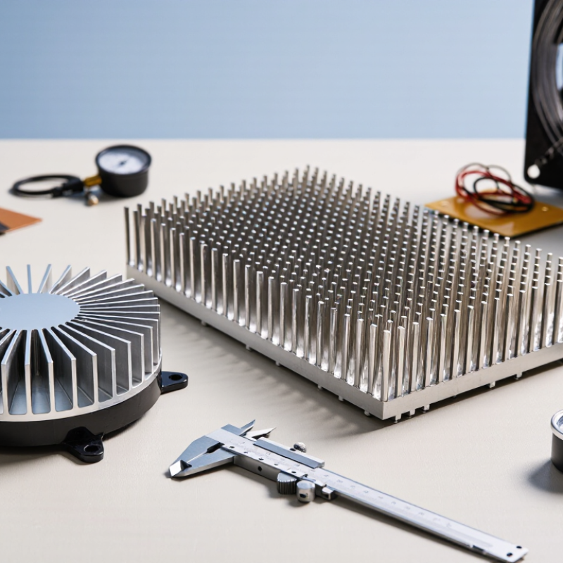
Choosing an Extruded Heat Sink in 2026 requires more than comparing catalog dimensions or surface finishes. The right profile must match the device’s real heat load, airflow, installation space, and operating environment. Small details matter.

A practical evaluation starts with thermal resistance, aluminum alloy, fin spacing, base thickness, and mounting pressure. For natural convection, widely spaced fins may perform better in dusty or low-airflow environments. Forced-air systems often benefit from denser fins, but only when fan pressure is sufficient. Fit comes first. A profile that looks efficient on paper may fail when screws, cables, or nearby components block airflow.

Reliable selection also depends on evidence. Request thermal test conditions, extrusion tolerances, alloy information, surface-treatment details, and production samples from the supplier. Compare performance using the same power input, ambient temperature, orientation, and airflow speed. Do not guess. A supplier’s simulation can be useful, but physical testing remains important because contact resistance and assembly variation can change results.

There is no universal best design. A compact heat sink may reduce enclosure size while increasing fan requirements. A larger profile may improve cooling but raise material cost and shipping weight. Engineers should also review corrosion exposure, noise limits, maintenance access, and expected product life. In 2026, responsible decisions will increasingly consider energy efficiency, recyclable aluminum, traceable manufacturing, and dependable technical support. Some early assumptions may prove wrong. That is normal. The strongest choice comes from measured data, honest constraints, and careful review before mass production.
How to Choose an Extruded Heat Sink in 2026?

Define Heat Load and Thermal Resistance Targets in W and °C/W

How to Choose an Extruded Heat Sink in 2026?

Define Heat Load and Thermal Resistance Targets in W and °C/W

Start with the heat load, not the heat sink shape. Add the power from every component that transfers heat into the extrusion. A 75 W device may produce nearly 75 W of thermal load during sustained operation. Measure it under the worst realistic workload, not during a brief startup test.

Next, define the allowable temperature rise. If the junction limit is 125°C and the enclosure can reach 45°C, the total thermal resistance target is 1.07°C/W at 75 W. The calculation is simple: (125 − 45) ÷ 75. That value includes the device interface, mounting layer, heat sink, and surrounding airflow. A common mistake is assigning the entire budget to the extrusion.

Keep margin.

For field equipment, a lower target may be wiser. An extrusion rated at 0.8°C/W could become less effective when dust blocks airflow or mounting orientation changes. Check the test conditions carefully. Natural convection and forced airflow produce very different results. Verify the published resistance with your actual fin direction, contact area, enclosure clearance, and fan speed.

I have seen designs pass bench tests but fail inside sealed cabinets. The thermal model looked convincing, yet the cabinet air stayed warmer than expected. Recalculate using measured case temperature when possible. Then select the extrusion length and fin profile that meet the °C/W target without relying on perfect contact or ideal airflow.

How to Choose an Extruded Heat Sink in 2026? - Define Heat Load and Thermal Resistance Targets in W and °C/W

Use the heat load and allowable temperature rise to establish a thermal-resistance target before selecting an extruded aluminum profile.

Design Case Heat Load
(W)
Design Ambient
(°C)
Maximum Heat-Sink Temperature
(°C)
Allowable Temperature Rise
(°C)
Target Heat-Sink-to-Ambient Resistance
(°C/W)
Recommended Cooling Mode Extruded Heat-Sink Selection Guidance
Low-power electronics 10 W 25 65 40 ≤ 4.00 °C/W Natural convection Use a compact profile with vertical fins and unobstructed airflow. Confirm that nearby components do not restrict convection.
Compact embedded controller 25 W 25 65 40 ≤ 1.60 °C/W Natural convection Choose a medium fin area, maintain vertical fin orientation, and provide clearance around the heat sink.
Power conversion module 50 W 25 65 40 ≤ 0.80 °C/W Natural convection or low-speed airflow Use a taller or denser fin profile. Low-speed forced airflow may be required when enclosure ventilation is limited.
Industrial power electronics 100 W 25 65 40 ≤ 0.40 °C/W Forced convection recommended Specify the airflow direction and minimum air velocity. Verify pressure drop, fan performance, and fin spacing together.
High-power converter 150 W 25 65 40 ≤ 0.27 °C/W Forced convection Use a high-surface-area extrusion with controlled airflow. Check mounting flatness and the thermal interface resistance.
High-density power assembly 200 W 25 65 40 ≤ 0.20 °C/W Forced convection or liquid-assisted design Use a large-profile extrusion with verified airflow distribution. If size, noise, or ambient temperature is restrictive, evaluate a liquid-cooled solution.

Core calculation: RθSA = (Tsink,max − Tambient) ÷ Q

Example: For 100 W with a 40 °C allowable temperature rise, the target is 40 ÷ 100 = 0.40 °C/W or lower.

Engineering note: These are system-level design targets, not guaranteed performance values for a particular extrusion. Actual thermal resistance depends on fin geometry, orientation, airflow, mounting pressure, interface material, surface finish, enclosure conditions, and heat-source distribution.

Design margin: Select a heat sink with a measured or simulated resistance below the calculated limit, commonly allowing approximately 15–25% margin for manufacturing variation, dust, airflow uncertainty, and rising ambient temperature.

Compare 6063-T5 Aluminum Conductivity at Approximately 201 W/m·K

How to Choose an Extruded Heat Sink in 2026?

6063-T5 aluminum offers thermal conductivity of approximately 201 W/m·K. This value makes it a practical choice for many extruded heat sinks. It transfers heat efficiently from a device into the fins. However, conductivity alone does not determine cooling performance. Fin height, thickness, spacing, and airflow also matter.

During thermal checks, I compare the heat source footprint with the sink’s base area. A thin base may reduce weight, but it can spread heat less evenly. A wider base often improves contact across several components. Surface flatness matters too. Small gaps increase thermal resistance. Use a suitable thermal interface material, then control mounting pressure carefully.

Airflow changes the result significantly. Closely packed fins can perform well with forced air, but they may restrict natural convection. For passive cooling, I usually inspect fin spacing before chasing maximum surface area. The stated 201 W/m·K figure may also vary with temperature, testing method, and material certification. Do not treat it as a guaranteed system result.

Real assemblies are less perfect. Dust, tilted mounting, and uneven contact can reduce performance. I would request a material certificate and review the manufacturer’s thermal-resistance data. Then test a prototype under the expected load, enclosure temperature, and airflow. A calculator helps, but measured temperatures reveal the uncomfortable details.

How to Choose an Extruded Heat Sink in 2026?

Thermal conductivity comparison of commonly used aluminum grades

6063-T5 aluminum has a typical thermal conductivity of approximately 201 W/m·K, making it a strong choice for many extruded heat sinks because it combines good heat transfer, extrusion performance, surface finish, and corrosion resistance. Actual values may vary with composition, temper, temperature, and supplier specifications.

Values shown are representative room-temperature conductivity figures for commonly referenced aluminum alloys.

Optimize Fin Height, Thickness, and Spacing for Natural Convection

In 2026, choosing an extruded heat sink starts with the air around it, not the catalog drawing. Natural convection depends on buoyancy, so fin channels need a clear vertical path for warm air. Measure the enclosure, nearby walls, cable bundles, and expected ambient temperature. A compact profile can fail when its outlet is blocked. I have seen this happen.

Fin height increases surface area, but taller fins also raise airflow resistance and may develop uneven temperatures. For still air, moderate height often performs better than a dense, oversized profile. Fin thickness must balance heat spreading, extrusion limits, and weight. Thin fins save material, yet they can create hot bases or deform during assembly. Spacing is equally important. Narrow gaps add area until boundary layers overlap; wider gaps improve chimney flow but reduce available surface. Start with reliable thermal data, then verify it under the actual mounting orientation.

Use a simple thermal model before selecting dimensions: estimate heat load, base temperature, ambient temperature, and allowable rise. Compare several height-to-gap ratios, rather than trusting one advertised resistance value. A practical prototype with thermocouples can reveal blocked airflow, contact resistance, or a surprisingly warm corner. Test at the highest realistic ambient temperature and with low airflow. Do not treat a room fan as natural convection. Extrusion direction, surface finish, and mounting pressure also affect results. The first design may be wrong. That is useful evidence. Record the error, adjust one variable, and test again.

Calculate Airflow, Interface Resistance, and Junction Temperatures

How to Choose an Extruded Heat Sink in 2026?

Calculate Airflow, Interface Resistance, and Junction Temperatures

Selecting an extruded heat sink starts with the heat load, ambient temperature, and available airflow. Measure real airflow near the enclosure, not only the fan’s advertised rating. Convert volumetric flow into air velocity across the fin area. Higher velocity usually improves convection, but turbulence and restricted vents can reduce performance. Use the relationship Q = hAΔT as a design guide, then verify the heat sink’s thermal curve under similar airflow conditions.

Interface resistance deserves equal attention. Calculate Rθcs from thermal interface material thickness, conductivity, and contact area. A thin layer often performs better than a thick one, but only with controlled pressure and reasonably flat surfaces. Mounting gaps, uneven screws, and excessive compound can quietly increase resistance. Keep the details visible.

Estimate junction temperature with Tj = Ta + P(Rθjc + Rθcs + Rθsa). For example, a 60-watt device and a 45°C ambient temperature can exceed safe limits when airflow falls below the test condition. My early calculations often looked too optimistic. The mistake was trusting nominal airflow and ignoring dust, cable blockage, and orientation.

Leave a practical margin, then test the assembly with thermocouples near the case and junction model. A spreadsheet helps. It is not evidence.

Recheck the result after enclosure testing, because the chosen extrusion may cool well on the bench but struggle inside the product.

Verify RoHS, REACH, UL 94, and 2026 Thermal Design Requirements

Choosing an extruded heat sink in 2026 requires more than comparing fin height and surface area. Start with compliance evidence. Request a current RoHS declaration, REACH substance statement, and UL 94 flammability rating for the insulation or nearby polymer parts. These documents should identify the tested material, revision date, and applicable product scope. Do not accept a generic certificate without checking its traceability.

Thermal verification must match the real assembly. Measure device power, expected ambient temperature, airflow direction, mounting pressure, and interface resistance. Then calculate the required thermal resistance, including transient loads and dust buildup. A heat sink that performs well in a clean laboratory may struggle inside a sealed enclosure. In 2026 designs, higher power density and compact electronics make junction-temperature margins especially important. Keep a practical safety margin.

I have seen projects fail because engineers reviewed only the aluminum profile. The interface pad compressed unevenly, adding several degrees of temperature rise. Recheck it. Ask for thermal test conditions, not only headline performance numbers. Confirm alloy, temper, anodizing, dimensional tolerances, and production consistency. I also verify that compliance documents match the final finish, coating, and assembly materials. Requirements can vary by market and application, so review the latest applicable standards before release. A small documentation gap can delay an otherwise sound design.