Why Choose Steel Cable Tray for Global Projects?
Why Choose Steel Cable Tray for Global Projects?
Global infrastructure projects demand cable support systems that remain dependable across different climates, building types, and installation practices. Steel Cable Tray is often selected because it provides strong mechanical support for power, control, and communication cables. Its rigid structure helps maintain orderly routes through factories, airports, data centers, and commercial buildings. That order matters when technicians inspect hundreds of meters of wiring.
Field experience shows that material selection cannot rely on price alone. Engineers must consider load capacity, span length, corrosion exposure, fire protection, grounding requirements, and local installation standards. A tray installed near a coastal plant may face salty air, while one inside a dry warehouse may face dust and vibration. Galvanized, stainless, or coated steel may suit different conditions. The wrong finish can reduce service life.
Details matter.
This article explores why Steel Cable Tray remains a practical choice for international projects. It considers structural strength, routing flexibility, installation efficiency, maintenance access, and long-term reliability. It also recognizes an uncomfortable point: steel is not automatically the best option everywhere. Weight, handling requirements, and corrosion risks deserve honest evaluation. Project teams should verify specifications with qualified engineers and compare regional codes before procurement. Reliable decisions come from documented testing, supplier transparency, and lessons recorded during real installations—not from attractive claims alone. Properties may vary between manufacturers. That is worth remembering.
Steel Cable Tray: Definition, Structure, and Core Functions
Steel Cable Tray: Definition, Structure, and Core Functions
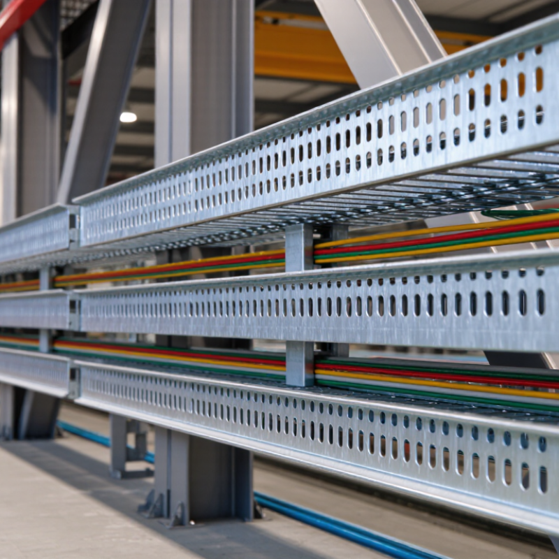
Steel cable tray is an open support system for power, control, and communication cables. It routes cables above floors, walls, and equipment. Its structure usually includes side rails, rungs or a solid base, couplers, covers, and support brackets. That simplicity matters. Installers can inspect cable routes without opening sealed conduits. In global projects, this improves maintenance access and reduces routing confusion.
Steel offers high mechanical strength for heavy cable loads and long support spans. Hot-dip galvanizing helps resist corrosion, while stainless steel suits coastal or chemically aggressive environments. IEC 61537 covers important performance requirements, including load capacity, electrical continuity, and flame behavior. Designers must still check temperature, cable weight, spacing, seismic movement, and local fire requirements. One weak calculation can compromise an entire route.
Global infrastructure is increasing cable demand. The International Energy Agency’s Electricity 2024 report estimates data-center electricity use reached about 460 TWh in 2022. It could exceed 1,000 TWh by 2026. Grand View Research also forecasts roughly 8% annual growth for the cable tray market through 2030. These figures support wider use, but growth does not make every tray suitable. Field inspections often find overcrowded bends, missing covers, or poorly bonded joints. Steel cable tray works best when its structure and installation details receive equal attention.
Why Steel Cable Tray Fits Diverse Global Project Environments
Steel cable tray fits diverse global project environments because it adapts to changing loads, climates, and installation methods. On a coastal site, galvanized steel helps resist moisture and salt exposure. In an industrial plant, its rigid structure supports heavy power and control cables. Engineers can select ladder, perforated, or solid-bottom designs according to ventilation and protection needs. That choice matters. A poorly matched tray creates heat, crowding, and maintenance problems.
Field experience shows that route planning is as important as material selection. Installers measure spans, cable fill, access points, and future capacity before fixing supports. Steel trays tolerate mechanical impact better than many lighter alternatives, especially near service corridors and equipment rooms. They also provide a dependable path for bonding when joints, fittings, and earthing details are properly designed. However, steel is not automatically suitable everywhere. Aggressive chemicals, unusual humidity, or limited lifting equipment may demand coatings, stainless grades, or lighter sections. This is where project assumptions need testing.
Global work also requires clear drawings, consistent dimensions, and inspection records that local crews can use. Metric measurements may cross with imperial equipment, causing avoidable fitting errors. Simple labels and verified connection points reduce confusion during installation and later repairs. Designers should check regional standards, fire requirements, seismic conditions, and available replacement parts. A small oversight can delay a whole cable route. During inspection, installers should record support spacing, joint continuity, and visible coating damage before cables conceal the tray.
Key Benefits for Cable Protection, Load Support, and System Safety
Steel cable tray gives global projects a practical shield for power and control cables. Its open profile improves airflow, while steel resists impact, abrasion, and accidental tool contact. That matters in factories, tunnels, and crowded utility rooms.
Load design needs evidence, not guesswork. NEMA VE 1-2023 lists common tray load classes from 50 to 200 pounds per foot, tested over defined support spans. IEC 61537:2023 also evaluates mechanical load, impact, and electrical continuity. These figures help engineers select a tray before cables arrive. They do not replace site calculations. A 3-meter span, vertical drop, or heavy cable bundle can change the result quickly.
Protection includes routing discipline. NFPA 70, 2023 Edition, Article 392 addresses cable-tray installation, grounding, fill, and support. Bonded steel sections can support a dependable grounding path when joints, fittings, and connections are installed correctly. Small details matter. Sharp edges need attention. Unused openings should not collect water or debris. In my project reviews, the weakest point is often not the tray body. It is an overlooked splice, undersized support, or future cable added without checking capacity. That deserves honest rethinking. A tray may look oversized today, yet expansion can consume its safety margin within months.
How to Select the Right Steel Cable Tray for Project Requirements
Choosing steel cable tray for a global project is not simply a price decision. The correct selection begins with the installation environment and cable schedule. Check cable weight, support spacing, span length, and future capacity. Measure twice. A tray carrying power cables needs more strength than one carrying light control wiring. Engineers should also review thermal conditions, vibration, seismic movement, and maintenance access. Small details matter.
For wet, coastal, or chemical areas, specify a corrosion-resistant finish or suitable stainless steel grade. Indoor dry rooms may need less protection, but assumptions should be documented. Perforated tray improves ventilation and offers flexible fixing points. Solid-bottom tray protects sensitive cables from falling dust, yet it can hold water if drainage is poor. That trade-off is easy to miss. Select covers, bends, tees, supports, and expansion connectors as one system. Mixing incompatible materials may accelerate galvanic corrosion.
Reliable projects verify the tray against applicable electrical and structural standards before procurement. Confirm bonding continuity, earthing provisions, fire performance, and separation between power and communication circuits. Review loading calculations, delivery conditions, lifting limits, and replacement access. On site, inspect cut edges, fasteners, joint alignment, and support anchors. Small installation errors can reduce capacity. I have seen technically sound drawings ignore local labor methods. Revise details when evidence disagrees. Ask installers to mock up one difficult section before full production. That imperfect test often exposes missing accessories, tight bends, or blocked maintenance routes.
Global Standards, Installation Practices, and Long-Term Maintenance
Why Choose Steel Cable Tray for Global Projects?
Global electrical demand is accelerating. The IEA Electricity 2024 report forecasts roughly 4% annual growth through 2026. Projects therefore need cable support systems that tolerate expansion, heat, vibration, and changing routes. Steel cable tray offers strong mechanical support and clear cable separation. Its open structure also improves inspection and airflow around power cables.
International projects require more than a strong product. IEC 61537 specifies performance tests for cable tray and ladder systems, including load capacity and electrical continuity. NEMA VE 2 provides practical guidance on supports, joints, bonding, and installation. Local codes still control the final design. Do not assume one standard fits every country. That mistake is common.
On site, installers should check span tables before loading trays. They should keep bend radii visible and avoid sharp edges near insulation. Bonding jumpers need attention at painted or discontinuous joints. A torque record helps, although records are often incomplete. That deserves improvement.
Tips: Use corrosion-resistant finishes after reviewing the site atmosphere. Separate power, control, and communication circuits where required. Mark spare capacity clearly. Leave room for future cables, but verify wind, seismic, and thermal loads. NEMA VE 2 recommends regular inspection, cleaning, and tightening. A six-month review can reveal loose covers, damaged coatings, or water accumulation before they become expensive failures.