


What Is a Steel CNC Machine and How Does It Work?
A steel CNC machine is a computer-controlled system that cuts, drills, mills, or turns steel with remarkable repeatability. It converts a digital design into coordinated mechanical movement. The result may be a small bracket, a bright shaft, or a heavy aerospace component with precisely measured holes.
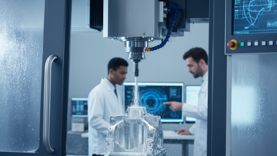
The process begins with a CAD model and a CAM program. The software creates toolpaths, cutting speeds, feed rates, and machine instructions. The controller then guides the spindle, cutting tool, and worktable along programmed axes. Coolant reduces heat, while clamping prevents the steel from shifting. Even a tiny setup error can leave visible chatter marks on a finished surface.
Professor Yusuf Altintas, a leading machining researcher, states, “Machining is a science of predicting and controlling material removal.” This principle explains why a steel CNC machine requires more than software. Tool geometry, steel hardness, vibration, temperature, and operator judgment all influence the final part.
The technology looks automatic.
It is not effortless.
A skilled machinist still checks tool wear, listens for unusual vibration, and measures the first component with calibrated equipment. Stainless steel may generate heat and work-hardening problems. Hardened steel can punish an unsuitable cutter within seconds. The machine may follow instructions perfectly, yet poor instructions produce poor results.
This guide examines what a steel CNC machine is, how its main components work, and why cutting parameters matter. It also considers practical limitations that product descriptions often ignore. Precision is achievable, but it is never accidental.
What Is a Steel CNC Machine?
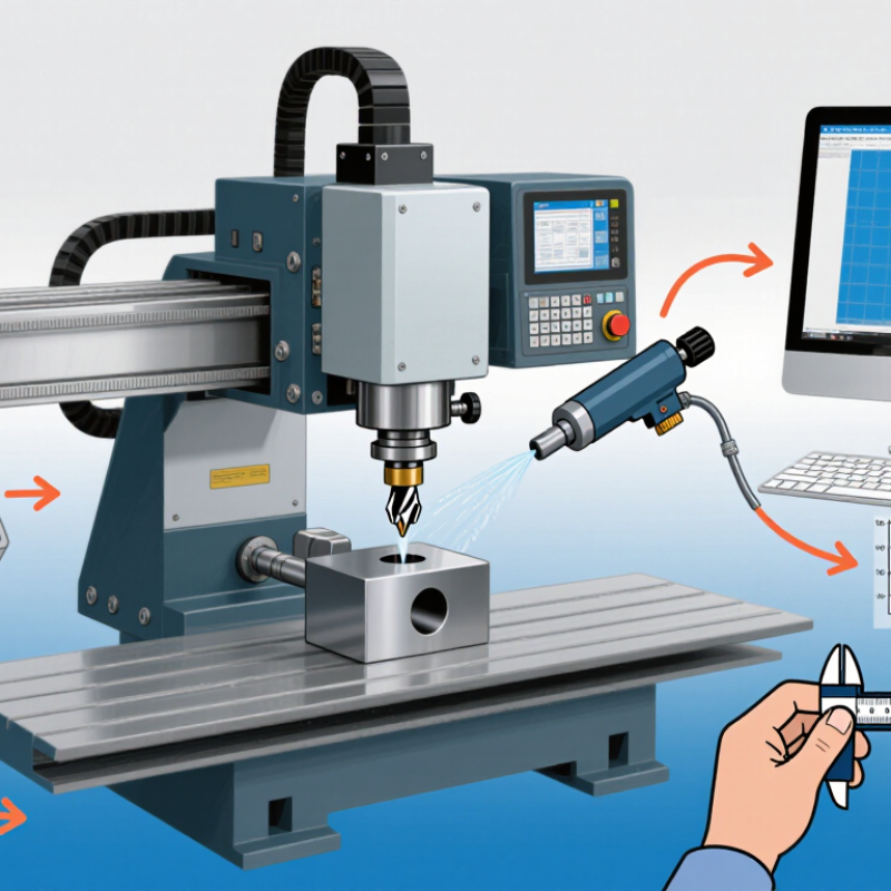
A steel CNC machine is a computer-controlled tool used to cut or shape steel parts with repeatable movements. CNC means computer numerical control. Common examples include milling machines, which use a rotating cutter, and lathes, which turn the workpiece against a cutting tool. The machine follows programmed coordinates, but it is not simply “hands-free.” Operators choose suitable tooling, secure the steel, and check the setup before cutting. Steel can place heavy loads on a cutter, so machine rigidity and correct cutting conditions matter.
A typical job starts with a part design and a toolpath created from it. The operator sets the workpiece, defines its position, and loads the program. The machine then moves its axes and controls the spindle to remove material in planned passes. Coolant may reduce heat and carry away chips. After machining, dimensions should be checked with appropriate measuring tools. In practice, the setup is not always as tidy as a diagram suggests; tool wear, vibration, or a poorly clamped part can affect the result. Small details matter.
Tips: Confirm the steel grade and thickness before choosing cutting tools and settings. Clamp the work securely, keep chips clear, and inspect the first finished part before running a larger batch.
| Topic | How It Works | Typical Details |
|---|---|---|
| Definition | A steel CNC machine uses computer numerical control (CNC) to guide cutting tools or other processing equipment along programmed paths to shape steel. | The machine type is chosen according to the required part shape, steel grade, production volume, and finishing needs. |
| Common machine types | CNC milling machines remove material with rotating cutters; CNC lathes turn a workpiece against a cutting tool; CNC laser, plasma, and waterjet machines cut sheet or plate. | Milling suits prismatic features, turning suits round components, and thermal or waterjet cutting suits profiles cut from sheet or plate. |
| Main components | A typical machining center includes a machine frame, spindle, axes, worktable, tool holder, CNC controller, and guarding. Many machines also use coolant and chip-removal systems. | The spindle drives the cutting tool, while the axes position the tool and workpiece. The controller interprets the programmed toolpath. |
| Axes and movement | Three-axis milling commonly moves along X, Y, and Z. Additional rotary axes can orient the tool or workpiece for more complex features. | Axis layout and travel vary by machine. More axes can reduce repositioning, but do not automatically guarantee greater accuracy. |
| Typical operations | Steel CNC machining can include face milling, slotting, drilling, boring, tapping, turning, and contour cutting. | The selected operation depends on the feature: drilling creates holes, tapping forms internal threads, and milling or turning produces surfaces and profiles. |
| Workholding | Clamps, vises, fixtures, or lathe chucks secure the steel during processing. | Secure, correctly aligned workholding helps limit movement and vibration. The method must suit the workpiece shape and cutting forces. |
| Cutting tools | Steel is commonly machined with carbide or high-speed steel cutting tools selected for the operation and material. | Tool geometry, coating, and cutting conditions should match the steel grade and hardness. Stainless, carbon, and alloy steels can machine differently. |
| Programming and setup | A part design is converted into toolpaths, often using computer-aided manufacturing (CAM) software. The operator sets work coordinates, tools, and cutting conditions before running the program. | The program specifies movements and operations; setup checks help confirm tool offsets, workpiece position, and safe clearances. |
| Machining cycle | The machine follows the programmed path while the tool and workpiece move relative to one another. Cutting removes material as chips, or as kerf in processes such as laser and plasma cutting. | Coolant may be used in machining to manage heat and assist chip removal. Its use depends on the process, material, and tooling. |
| Accuracy and finish | Achievable dimensions and surface finish depend on the machine, tooling, workholding, material, program, and inspection method. | Tolerances should be specified on the part drawing and confirmed for the particular machine and process; there is no single accuracy value that applies to every steel CNC machine. |
Related Posts
-
7 Tips for Buying a CNC Machine?
-
Why Choose a CNC Machine for Your Manufacturing Needs?
-
2026 How to Choose the Best CNC Machining Solutions for Your Business?
-

Why Choose Prototype Manufacturing at the 139th Canton Fair?
-
How to Achieve CNC Precision in Manufacturing Processes?
-
Precision Milling Top Tips for Global Buyers in 2026