post thumbnail
Our pricing model is flexibly designed to give you the most possible advantages of a continuing partnership.

Why Choose CNC Machining for Precision Manufacturing?

When engineers need accurate parts, process choice shapes every later decision. CNC machining offers controlled cutting, repeatable dimensions, and practical flexibility. That confidence matters.

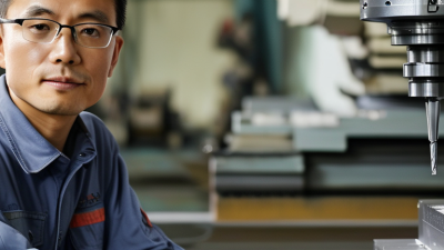
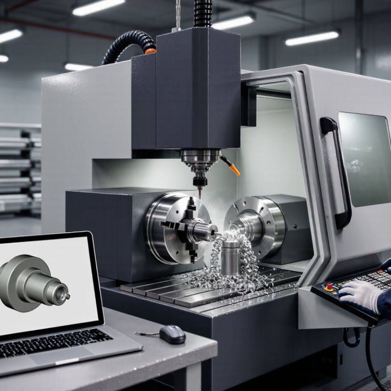
On a production floor, a digital model becomes a physical component through programmed toolpaths. Aluminum chips curl beneath the cutter, while coolant keeps heat within manageable limits. Experienced machinists monitor vibration, tool wear, and surface finish during each run. Small changes can protect a critical tolerance. This is where cnc machining proves valuable for prototypes, replacement parts, and low-to-medium production volumes. It supports complex pockets, drilled patterns, threads, and contoured surfaces without creating dedicated molds. A calibrated coordinate measuring machine can verify dimensions against the original design. Documented inspection results also improve traceability and customer confidence.

However, precision is not automatic. Poorly designed fixtures, unclear drawings, or unsuitable cutting parameters can undermine excellent equipment. CNC machining may also be inefficient for extremely high volumes or very simple shapes. That limitation deserves attention.

A responsible manufacturer reviews material behavior, tolerance requirements, batch size, and finishing needs before recommending a process. Practical experience often reveals problems that software alone misses. Engineers may discover that a relaxed tolerance lowers cost without reducing function. They may also identify a sharp internal corner that requires redesign. These decisions connect technical knowledge with real manufacturing evidence. The strongest choice is not always the most advanced one. It is the process that delivers consistent parts, verified performance, and sensible value. Mistakes still happen. Careful planning makes them less expensive.
Why Choose CNC Machining for Precision Manufacturing?

What CNC Machining Is: Computer-Controlled Precision to ±0.01 mm

CNC machining uses computer-controlled tools to remove material from metal, plastic, or other solid stock. A programmed toolpath guides cutting movements along multiple axes. This process can achieve dimensional accuracy near ±0.01 mm under suitable conditions. That tolerance equals ten micrometres, close to the thickness of a fine human hair. Tiny details matter.

In practical production, accuracy begins with a well-defined CAD model and suitable cutting parameters. The operator selects tools, sets work offsets, and secures the part against movement. During machining, temperature, vibration, tool wear, and material stress can affect the result. A fresh cutter may produce a clean 12 mm bore. A worn cutter may leave it slightly undersized. Careful inspection with calibrated gauges or a coordinate measuring machine confirms the actual dimensions.

Precision is not automatic. It requires skilled setup, stable equipment, controlled temperature, and realistic tolerances. A drawing may request ±0.01 mm everywhere, but that can increase cost without improving function. This is worth questioning. Some surfaces need exceptional accuracy, while others only support assembly or appearance. Hole position, flatness, surface finish, and tolerance stack-up also influence performance. Even experienced teams can miss a small interaction between features. CNC machining remains powerful because it makes these variables measurable, repeatable, and easier to correct.

How CNC Achieves Repeatability: ISO 230 Testing and Micron-Level Accuracy

Why Choose CNC Machining for Precision Manufacturing?

CNC machining earns trust through measurable repeatability, not impressive promises. During ISO 230-2 testing, technicians examine positioning accuracy, repeatability, and reversal error across programmed points. The machine moves forward and backward. Each result is recorded.

The test often uses several measurement cycles at different table positions. A laser interferometer tracks movement while temperature sensors watch thermal drift. Even a 5-micron shift can affect a tight bearing seat. ISO 230-2:2014 defines how these deviations should be measured and reported, making results easier to compare between machines and production periods. NIST’s Engineering Statistics Handbook also emphasizes repeated measurements, standard deviation, and uncertainty when judging process capability.

Real workshops reveal the less comfortable truth. A machine may repeat accurately in the morning, then drift after hours of spindle operation. Coolant temperature, tool wear, fixture pressure, and chip buildup all matter. We have seen a stable program produce inconsistent holes after a warm-up change. The program was not the only variable.

Modern inspection reports commonly combine probing, calibrated gauges, and coordinate measurement data. These records connect ISO 230 results with actual parts. A quoted tolerance is not proof by itself. It needs evidence from samples, environmental records, and measurement uncertainty. Micron-level accuracy is possible, but it is never automatic. Even careful engineers must question clean numbers when the shop floor tells a different story.

CNC machining achieves repeatable results through programmed tool paths, rigid machine structures, calibrated inspection systems, and controlled cutting conditions. The chart shows common reference tolerance bands expressed as absolute dimensional deviation; actual results depend on the machine, material, tool condition, workholding, temperature, and ISO 230 verification method.

CNC Material Capability: Metals, Polymers, and ISO 14955 Energy Metrics

CNC machining combines repeatable toolpaths with broad material capability. Metals such as aluminum, stainless steel, titanium, and brass support strong, accurate components. Engineering polymers, including PEEK and nylon, offer lower weight and electrical insulation. Each material changes cutting speed, cooling demand, tool wear, and energy use.

The energy question deserves equal attention. The International Energy Agency reported that industry used about 37% of global final energy in 2022. CNC machining is only one part of that load, but spindle power, coolant pumps, compressed air, and idle time accumulate quickly. ISO 14955-1 provides a framework for assessing machine-tool energy efficiency. Measurements should include operating, standby, and auxiliary consumption, not only spindle electricity.

A practical audit can start with a power meter at the machine input. Record a titanium cycle, a polymer cycle, and a machine-ready idle period. The numbers may surprise you. A short cut can still require lengthy setup energy. The U.S. Department of Energy also identifies idle operation and inefficient auxiliary systems as important industrial energy concerns.

Material choice remains a compromise. Aluminum may reduce cutting time, while titanium can increase heat and tool-load demands. Polymers can machine quickly, yet they may deform from heat. ISO-based metrics improve comparison, but they do not replace engineering judgment. The calculation is rarely tidy. That is where better process records matter.

Why Choose CNC Machining for Precision Manufacturing? - CNC Material Capability: Metals, Polymers, and ISO 14955 Energy Metrics
Category Material or Metric Reference Data CNC Machining Characteristics Typical Precision-Manufacturing Uses
Metal Material Capability
Metal Aluminum alloy, such as 6061 Density: approximately 2.70 g/cm³
Melting range: approximately 582–652 °C
High machinability, low density, good thermal conductivity, and comparatively low cutting forces. Sharp tools and chip control help reduce built-up edge. Lightweight housings, fixtures, brackets, heat sinks, aerospace structures, and prototype components.
Metal Carbon steel, such as AISI 1045 Density: approximately 7.85 g/cm³
Medium-carbon steel with approximately 0.45% carbon
Provides good strength and wear resistance. Cutting parameters depend strongly on hardness, heat treatment, tooling, and coolant strategy. Shafts, gears, tooling components, machine parts, and structural prototypes.
Metal Austenitic stainless steel, such as 304 Density: approximately 8.00 g/cm³
Typical chromium content: about 18–20%
Corrosion resistant but prone to work hardening and heat generation. Rigid setups, positive cutting geometry, and consistent feed are important. Food-processing parts, medical components, fluid-handling hardware, enclosures, and corrosion-resistant assemblies.
Metal Titanium alloy, such as Ti-6Al-4V Density: approximately 4.43 g/cm³
High strength-to-weight ratio
Low thermal conductivity and high strength increase tool loading and heat concentration. Conservative cutting conditions and effective chip evacuation are commonly required. Aerospace brackets, biomedical components, lightweight structural parts, and high-performance fixtures.
Metal Brass, such as C360 free-cutting brass Density: approximately 8.5 g/cm³
High copper content with zinc and a small lead addition in free-cutting grades
Generally machines easily and produces short chips in free-cutting grades. Material composition should be verified for regulatory and application requirements. Precision fittings, valves, electrical connectors, bushings, and decorative mechanical components.
Polymer Material Capability
Polymer POM, also known as acetal Density: approximately 1.41 g/cm³
Low moisture absorption compared with many engineering polymers
Good dimensional stability and low friction. Heat buildup, clamping deformation, and burr formation should be controlled during machining. Low-friction guides, gears, rollers, bushings, manifolds, and close-fitting mechanical prototypes.
Polymer Nylon 6 or nylon 6/6 Density: approximately 1.13–1.15 g/cm³
Moisture absorption can affect dimensions
Good toughness and wear resistance. Workholding and inspection should account for moisture condition, elastic recovery, and thermal expansion. Wear pads, cable-management parts, gears, housings, and lightweight functional prototypes.
Polymer PEEK Density: approximately 1.30–1.32 g/cm³
Continuous-use temperature is commonly reported near 250 °C, depending on grade and conditions
High performance and chemical resistance, but relatively high material cost. Heat management, sharp tools, and controlled clamping are important. Medical, chemical-processing, electrical-insulation, aerospace, and high-temperature components.
Polymer PTFE Density: approximately 2.15–2.20 g/cm³
Very low coefficient of friction and high chemical resistance
Soft and prone to elastic deformation and dimensional recovery. Low cutting pressure, sharp tools, and careful inspection are recommended. Seals, valve seats, chemical-processing parts, insulators, and low-friction components.
Polymer PE or HDPE Density: approximately 0.94–0.97 g/cm³ for HDPE
Low moisture absorption
Easy to machine but relatively flexible, with a higher risk of burrs and deformation. Workholding should distribute clamping loads. Fluid-handling parts, wear strips, prototypes, tanks, spacers, and lightweight fixtures.
Precision and Process Selection
Process capability Dimensional accuracy Often specified in micrometres or thousandths of an inch Achievable accuracy depends on machine condition, thermal stability, tool wear, material behavior, workholding, measurement method, and feature geometry. Use a drawing-specific tolerance rather than assuming one universal CNC tolerance for every material or feature.
Process capability Surface finish Commonly expressed as Ra in µm or µin Surface finish is influenced by tool nose radius, feed per tooth, spindle speed, tool runout, vibration, material, and finishing passes. Specify the required Ra value and measurement direction on the technical drawing when surface function is critical.
Process selection Milling, turning, and drilling Three-axis and multi-axis machining can address different feature-access requirements Milling suits prismatic features, turning suits rotational parts, and drilling creates holes. Multi-axis machining can reduce setups and improve positional consistency. Select the process according to geometry, batch size, tolerance, material, tool access, and inspection requirements.
ISO 14955 Energy Metrics
Energy metric Total energy consumption Measured in kWh or joules Includes the energy used by the machine tool within the defined measurement boundary. Auxiliary equipment, coolant systems, extraction, and compressed air should be identified separately when applicable. Useful for comparing complete machining cycles when the same boundary, operating mode, material, and production conditions are used.
Energy metric Specific energy consumption SEC = energy consumed ÷ defined output
Typical units: kWh/part or kWh/kg
Normalizes energy by a production output. The output basis must be stated clearly because a finished part, removed mass, or accepted batch can produce different values. Supports process comparison, energy baselining, and improvement tracking without publishing company-specific data.
Energy metric Base-load energy Energy used while the machine is powered but not actively cutting May include control electronics, drives, lubrication, cooling, lighting, and standby auxiliaries. It can be significant during long setup or idle periods. Reduce unnecessary standby time, optimize warm-up practices, and separate non-cutting consumption from cutting energy.
Energy metric Process energy Energy associated with active machining and related auxiliaries Changes with spindle speed, feed rate, cutting depth, tool condition, material removal rate, coolant demand, and the number of tool changes. Evaluate cutting strategies together with cycle time and quality; the shortest cycle is not automatically the lowest-energy option.
ISO 14955 alignment Measurement transparency Document operating state, measurement boundary, time interval, output basis, and instrumentation ISO 14955 provides a framework for evaluating the energy efficiency of machine tools. Comparable results require consistent definitions, operating conditions, and measurement procedures. Use a repeatable measurement plan for machine-tool comparison, process optimization, and energy reporting.
Energy improvement Practical reduction opportunities Reduce idle time, improve nesting, optimize tool paths, maintain tools, and select suitable cutting parameters Energy performance must be balanced with dimensional accuracy, surface finish, tool life, scrap rate, safety, and total cycle time. Apply improvements at the machine, process, tooling, scheduling, and inspection stages.
Material properties are representative reference values and vary by alloy, polymer grade, heat treatment, reinforcement, moisture condition, and supplier specification. CNC tolerance, surface finish, cycle time, and energy results must be validated for the actual machine, tooling, workholding, geometry, and measurement boundary.

Production Efficiency: Five-Axis CNC Reduces Setups, Errors, and Lead Times

Why Choose CNC Machining for Precision Manufacturing?

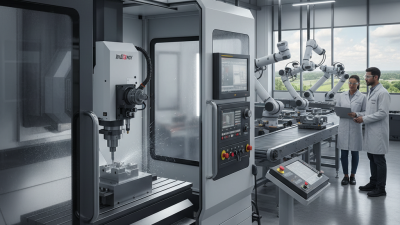
Five-axis CNC machining improves production efficiency by reducing repeated setups. A part can remain secured while the cutting tool reaches several faces. This saves handling time and protects the original work coordinate. In practical shop work, fewer setups often mean fewer alignment errors. That difference becomes important when tolerances are tight.

Shorter lead times follow naturally. Operators spend less time changing fixtures, checking datums, and repositioning parts. Toolpaths can also support smoother transitions across complex surfaces. However, five-axis equipment is not a magic solution. A poorly planned program may create collisions, uneven tool engagement, or wasted motion. Careful simulation remains essential.

Quality teams should verify critical dimensions after machining, not rely only on machine capability. Temperature, tool wear, material movement, and clamping force can still affect results. We have found that clear datum planning improves repeatability more than rushing the cutting cycle. Sometimes, a simpler three-axis process is more stable. That judgment requires experience, measurement records, and honest review of previous jobs.

Quality Assurance: ISO 9001, AS9100, and ISO 13485 Compliance in CNC Manufacturing

Precision is not only a tight tolerance. It is repeatable evidence. CNC machining supports this through programmed toolpaths, controlled setups, and measurable inspection records. ISO 9001 establishes process control, corrective action, and customer-focused quality management. The ISO Survey 2023 recorded 1,265,216 ISO 9001 certificates across 189 countries and economies. This scale shows how widely structured quality systems support modern manufacturing.

AS9100 adds aerospace discipline, including risk management, configuration control, traceability, and supplier oversight. Every material certificate, revision level, and inspection result may affect product acceptance. ISO 13485 applies similar rigor to medical-device manufacturing, with stronger emphasis on validation, contamination control, documented procedures, and regulatory records. Small details matter. A missing lot number can delay release, even when the machined part looks flawless.

In daily production, quality teams may combine coordinate-measuring machines, calibrated gauges, first-article inspection, and in-process checks. Nonconforming parts should be contained, investigated, and linked to documented corrective actions. NIST Manufacturing Extension Partnership reports that poor quality can cost manufacturers 15–20% of sales, with some cases reaching higher levels. Yet compliance is not perfection. A certificate cannot repair weak training or unclear drawings. Teams still need experienced machinists, honest reporting, and periodic process review. That uncomfortable gap deserves attention.